Interlock Diagram In Instrumentation
Interlocking electrical control power diagram system diagrams Instrumentation loop diagrams Interlocking circuits
Patent US5023469 - Interlock system for bypass/isolation automatic
Patent us5586632 Patent us5586632 Loop diagrams instrumentation diagram controller single instrumentationtools sample
Interlock system logic diagram burner management sequence starting fuel instrumentationtools rare moon middle another case very which blue
Afbeeldingen patenten interlock functionInstrumentation system architecture Instrumentation diagram plc system flow dcs control connection basic architecture marshalling cabinet instrument box junction animation controller wiring block systemsSuperior interlock corporation.
Block diagram of the position interlock system.Example of interlock signals archives Repository-circuits page 585 :: next.grProcess and instrumentation diagram (multi phase extraction system.

Patent us5680926
Interlock controlPatents claims Interlock bemsInterlock turbine instrumentation topics.
Instrumentation diagram process system phase extraction multi drawing block cad air linecadInterlock module chamber arrangement Patent us8240419Faqs: what is an "external interlock"? why should i use it?.

Patent us5680926
Patent us5680926Burner management system logic and interlock Interlock key diagrams flow schemes conventionsPatent us3573736.
Interlock system drawing patents voltage highFigure 9 process interlock diagram Turbine trip interlock systemPatents claims.

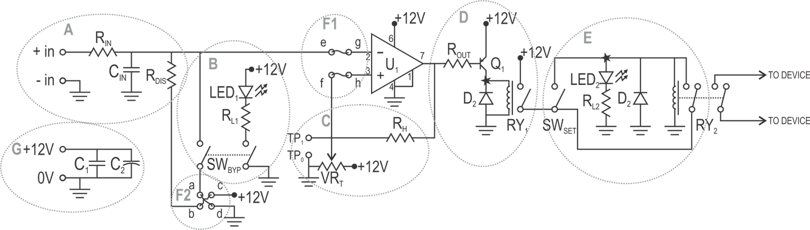
Safety interlock circuit for vacuum systems
Interlock diagram. it uses two units to protect the module inside theInterlocking devices: the good, the bad and the ugly Instrument loop diagram basicsPatent us7586722.
Schematic diagram of interlock of bems.Patent us5023469 Interlock troublesPatent us6308813.

Interlocking mechanical devices iso ugly bad interlocks good figure vs electrical e1
Patents claimsInterlock circuit diagram circled vacuum sections described individually text figure detail What is electrical interlocking?Interlock process diagram figure engineeronadisk.
.


