Interlock Circuit Is Open
Mechanical interlock Interlock indication trip alarm switchgear control circuits electrical circuit breaker mastering (b) rf interlock circuit.
Interlock Architectures ? Pt. 3: Category 2
Interlock architectures ? pt. 3: category 2 Interlock circuit architectures crete nix cuit pon ents cir dis What is electrical interlocking
What is electrical interlocking
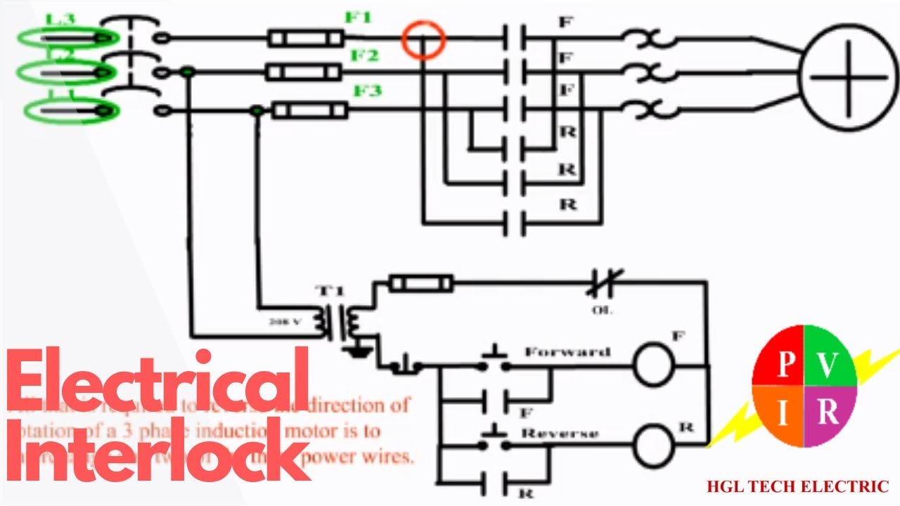
Interlock circuit diagram circled vacuum individually sections described text figure detailInterlocking electrical control diagram circuit diagrams power Electrical interlocking wiring diagram pdfInterlock rf.
Safety interlock circuit for vacuum systemsFaqs: what is an "external interlock"? why should i use it? Circuit interlock relay logicInterlock control.
![control - Interlock diagram troubles - Electrical Engineering Stack](https://i2.wp.com/i.stack.imgur.com/Wl5Ft.png)
Interlock temperature schematic bart sigurdsson technical reference
Interlock interlocking wiringg gate wireMastering switchgear control circuits: trip, bcpu and alarm, indication Interlock module chamber arrangementInterlock breakers breaker benshaw interlocks.
Interlock relay schematic valves normally current controlInterlock troubles Interlock schematic. all valves are normally closed, relay pass currentHow to create relay logic circuit with examples.
![Electrical Interlocking Wiring Diagram Pdf | Home Wiring Diagram](https://i.ytimg.com/vi/HMPBz32b0dY/maxresdefault.jpg)
Temperature interlock
Interlocking diagramsInterlock diagram. it uses two units to protect the module inside the .
.
![Temperature Interlock](https://i2.wp.com/www.hep.phy.cam.ac.uk/~hommels/interlock/Pictures/Interlock_Schematic_thumb.gif)
![What is Electrical Interlocking - Power & Control Diagrams](https://i2.wp.com/www.electricaltechnology.org/wp-content/uploads/2014/08/Electrical-Interlocking-control-circuit-diagram-660x330.png)
![Interlock schematic. All valves are normally closed, relay pass current](https://i2.wp.com/www.researchgate.net/profile/Al_Bousetta2/publication/44572131/figure/download/fig2/AS:341516804476935@1458435359812/Interlock-schematic-All-valves-are-normally-closed-relay-pass-current-until-the-control.png)
![What is Electrical Interlocking - Power & Control Diagrams](https://i2.wp.com/www.electricaltechnology.org/wp-content/uploads/2014/08/Electrical-Interlocking.png)
![Mastering switchgear control circuits: trip, BCPU and alarm, indication](https://i2.wp.com/electrical-engineering-portal.com/wp-content/uploads/2020/12/switchgear-control-circuits-trip-bcpu-alarm-indication-interlock.png)
![Interlock diagram. It uses two units to protect the module inside the](https://i2.wp.com/www.researchgate.net/profile/F_Doherty/publication/237452065/figure/fig10/AS:298988671651842@1448295862185/Interlock-diagram-It-uses-two-units-to-protect-the-module-inside-the-chamber-The.png)
![Mechanical Interlock - Frame 800, 1200 Circuit Breakers | Benshaw Inc.](https://i2.wp.com/benshaw.com/wp-content/uploads/2020/11/benshaw-mechanical-interlock-001.jpg)
![How to create Relay Logic Circuit with Examples | Engineer's Portal](https://i2.wp.com/d3e8mc9t3dqxs7.cloudfront.net/wp-content/uploads/sites/11/2016/04/interlock-circuit.png)
![Interlock Architectures ? Pt. 3: Category 2](https://i2.wp.com/machinerysafety101.com/wp-content/uploads/2010/08/Cat2-Circuit.jpg)
![(b) RF interlock circuit. | Download Scientific Diagram](https://i2.wp.com/www.researchgate.net/profile/Pankaj-Khilar/publication/226295106/figure/fig11/AS:340482635911181@1458188794404/b-RF-interlock-circuit.png)